Fonts
module Font : sig ... endFonts.
type font = Font.tThe type for fonts.
The type for glyphs. The integer represents a glyph identifier in a backend dependent font format.
Paths and images
x >> f is f x, associates to left. Used to build paths and compose images.
module P : sig ... endPaths.
module I : sig ... endImages.
Image renderers
module Vgr : sig ... endImage renderers.
Basics
Vg is designed to be opened in your module. This defines only types and modules in your scope. Thus to use Vg start with :
open Gg
open Vg
Gg gives us types for points (Gg.p2), vectors (Gg.v2), 2D extents (Gg.size2), rectangles (Gg.box2) and colors (Gg.color). Later you may want to read Gg's documentation basics but for now it is sufficient to know that each of these types has a constructor v in a module named after the capitalized type name (Gg.P2.v, Gg.V2.v, etc.).
A collage model
Usual vector graphics libraries follow a painter model in which paths are filled, stroked and blended on top of each other to produce a final image. Vg departs from that, it has a collage model in which paths define 2D areas in infinite images that are cut to define new infinite images to be blended on top of each other.
The collage model maps very well to a declarative imaging model. It is also very clear from a specification point of view, both mathematically and metaphorically. This cannot be said from the painter model where the semantics of an operation like stroking a self-intersecting translucent path — which usually applies the paint only once — doesn't directly map to the underlying paint stroke metaphor. The collage model is also more economical from a conceptual point view since image cuts and blends naturally unify the distinct concepts of clipping paths, path strokes, path fills and compositing groups (unsupported for now in Vg) of the painter model.
The collage model introduced in the following sections was stolen and adapted from the following works.
- Conal Elliott. Functional Image Synthesis, Proceedings of Bridges, 2001.
- Antony Courtney. Haven : Functional Vector Graphics, chapter 6 in Modeling User Interfaces in a Functional Language, Ph.D. Thesis, Yale University, 2004.
Infinite images
Images in Vg are immutable and abstract value of type image. Conceptually, images are seen as functions mapping points of the infinite 2D plane to colors:
type Vg.image ≈ Gg.p2 -> Gg.color
The simplest image is a constant image: an image that associates the same color to every point in the plane. For a constant gray of intensity 0.5 this would be expressed by the function:
fun _ -> Color.gray 0.5In Vg the combinator I.const represents constant infinite images and the above function is written:
let gray = I.const (Color.gray 0.5)The module I contains all the combinators to define and compose infinite images, we will explore some of them later. But for now let's just render that fascinating image.
Rendering
An infinite image alone cannot be rendered. We need a finite view rectangle and a specification of that view's physical size on the render target. These informations are coupled together with an image to form a renderable.
Renderables can be given to a renderer for display via the function render. Renderers are created with Vgr.create and need a render target value that defines the concrete renderer implementation used (PDF, SVG, HTML canvas etc.).
The following function outputs the unit square of gray on a 30x30 millimeters SVG target in the file /tmp/vg-basics.svg:
let svg_of_usquare i =
let size = Size2.v 30. 30. in
let view = Box2.unit in
try
let oc = open_out "/tmp/vg-basics.svg" in
let r = Vgr.create (Vgr_svg.target ()) (`Channel oc) in
try
ignore (Vgr.render r (`Image (size, view, i)));
ignore (Vgr.render r `End);
close_out oc
with e -> close_out oc; raise e
with Sys_error e -> prerr_endline e
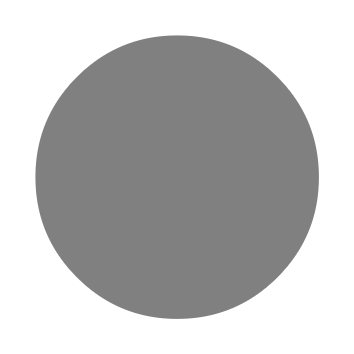
let () = svg_of_usquare grayThe result should be an SVG image with a gray square like this: 
Coordinate space
Vg's cartesian coordinate space has its origin at the bottom left with the x-axis pointing right, the y-axis pointing up. It has no units, you define what they mean to you. However a renderable implicitely defines a physical unit for Vg's coordinate space: the corners of the specified view rectangle are mapped on a rectangular area of the given physical size on the target.
Scissors and glue
Constant images can be boring. To make things more interesting Vg gives you scissors: the cut combinator.
This combinator takes a finite area of the plane defined by a path path (more on paths later) and a source image img to define the image I.cut path img that has the color of the source image in the area defined by the path and the invisible transparent black color (Gg.Color.void) everywhere else. In other words I.cut path img represents this function:
fun pt -> if inside path pt then img pt else Color.voidThe following code cuts a circle of radius 0.4 centered in the unit square in the gray image defined before.
let circle = P.empty |> P.circle (P2.v 0.5 0.5) 0.4
let gray_circle = I.cut circle gray
Rendered by svg_of_usquare the result is:
Note that the background white color surrounding the circle does not belong to the image itself, it is the color of the webpage background against which the image is composited. Your eyes require a wavelength there and Gg.Color.void cannot provide it.
cut has an optional area argument of type P.area that determines how a path should be interpreted as an area of the plane. The default value is `Anz, which means that it uses the non-zero winding number rule and for circle that defines its interior.
But the circle path can also be seen as defining a thin outline area around the ideal mathematical circle of circle. This can be specified by using an outline area `O o. The value o of type P.outline defines various parameters that define the outline area; for example its width. The following code cuts the circle outline area of width 0.04 in an infinite black image.
let circle_outline =
  let area = `O { P.o with P.width = 0.04 } in
  let black = I.const Color.black in
  I.cut ~area circle black
Below is the result and again, the white you see here is in fact Gg.Color.void.

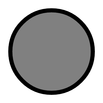
cut gives us scissors but to combine the results of cuts we need some glue: the blend combinator. This combinator takes two infinite images front and back and defines an image I.blend front back that has the colors of front alpha blended on top of those of back. I.blend front back represents this function:
let i' = fun pt -> Color.blend (front pt) (back pt)If we blend circle_outline on top of gray_circle:
let dot = I.blend circle_outline gray_circleWe get:
The order of arguments in blend is defined so that images can be blended using the left-associative composition operator |>. That is dot can also be written as follows:
let dot = gray_circle |> I.blend circle_outlineThis means that with |> and blend left to right order in code maps to back to front image blending.
Transforming images
The combinators I.move, I.rot, I.scale, and I.tr allow to perform arbitrary affine transformations on an image. For example the image I.move v i is i but translated by the vector v, that is the following function:
fun pt -> img (V2.(pt - v))The following example uses I.move. The function scatter_plot takes a list of points and returns a scatter plot of the points. First we define a dot around the origin, just a black circle of diameter pt_width. Second we define the function mark that given a point returns an image with dot at that point and blend_mark that blends a mark at a point on an image. Finally we blend all the marks toghether.
let scatter_plot pts pt_width =
  let dot =
    let circle = P.empty |> P.circle P2.o (0.5 *. pt_width) in
    I.const Color.black |> I.cut circle
  in
  let mark pt = dot |> I.move pt in
  let blend_mark acc pt = acc |> I.blend (mark pt) in
  List.fold_left blend_mark I.void pts
Note that dot is defined outside mark, this means that all marks share the same dot, doing so allows renderers to perform space and time optimizations. For example the SVG renderer will output a single circle path shared by all marks.
Here's the result of scatter_point on 800 points with coordinates on independent normal distributions. 
Paths
Paths are used to define areas of the plane. A path is an immutable value of type path which is a list of disconnected subpaths. A subpath is a list of directed and connected curved segments.
To build a path you start with the empty path P.empty, give it to P.sub to start a new subpath and give the result to P.line, P.qcurve, P.ccurve, P.earc or P.close to add a new segment and so forth.
Path combinators take the path they act upon as the last argument so that the left-associative operator |> can be used to construct paths.
The image below is made by cutting the outline of the single path p defined hereafter. 
let p =
  let rel = true in
  P.empty |>
  P.sub (P2.v 0.1 0.5) |>
    P.line (P2.v 0.3 0.5) |>
    P.qcurve ~rel (P2.v 0.2 0.5) (P2.v 0.2 0.0) |>
    P.ccurve ~rel (P2.v 0.0 (-. 0.5)) (P2.v 0.1 (-. 0.5)) (P2.v 0.3 0.0) |>
    P.earc ~rel (Size2.v 0.1 0.2) (P2.v 0.15 0.0) |>
  P.sub (P2.v 0.18 0.26) |>
    P.qcurve ~rel (P2.v (0.01) (-0.1)) (P2.v 0.1 (-. 0.05)) |>
    P.close |>
  P.sub (P2.v 0.65 0.8) |>
    P.line ~rel (P2.v 0.1 (-. 0.05))
in
let area = `O { P.o with P.width = 0.01 } in
I.const Color.black |> I.cut ~area p
Except for P.close which has no other argument but a path, the last point argument before the path argument is always the concrete end point of the segment. When true the optional rel argument indicates that the coordinates given to the constructor are expressed relative to end point of the last segment (or P2.o if there is no such segment).
Note that after a P.close or on the P.empty path, the call to P.sub can be omitted. In that case an implicit P.sub P2.o is introduced.
For more information about how paths are intepreted as areas, consult their semantics.
Remarks and tips
- Angles follow
Gg's conventions. - Matrices given to
P.trandI.trare supposed to be affine and as such ignore the last row of the matrix. to_stringfunctions are not thread-safe. Thread-safety can be achieved withppfunctions.- Do not rely on the output of printer functions, they are subject to change.
- Rendering results are undefined if path or image data contains NaNs or infinite floats.
- Any string is assumed to be UTF-8 encoded.
- Sharing (sub)image, path and outline values in the definition of an image may result in more efficient rendering in space and time.
Semantics
The following notations and definitions are used to give precise meaning to the images and the combinators.
Colors
The semantics of colors is the one ascribed to Gg.color: colors are in a linearized sRGBA space.
Color stops
A value of type Gg.Color.stops specifies a color at each point of the 1D unit space. It is defined by a list of pairs (ti, ci) where ti is a value from 0 to 1 and ci the corresponding color at that value. Colors at points between ti and ti+1 are linearly interpolated between ci and ci+1. If ti lies outside 0 to 1 or if ti-1 >= ti the semantics is undefined.
Given a stops value stops = [(t0, c0); (t1,c1); ... (tn, cn)] and any point t of 1D space, the semantic function:
[] : Gg.Color.stops -> float -> Gg.color
maps them to a color value written [stops]t as follows.
- []t =
(0, 0, 0, 0)for anyt - [
stops]t= c0 ift < t0. - [
stops]t= cn ift >= tn. - [
stops]t= (1-u)ci+ uci+1 withu = (t - ti)/(ti+1-ti)ifti<= t <ti+1
Images
Values of type image represent maps from the infinite 2D euclidian space to colors. Given an image i and a point pt of the plane the semantic function
[]: image -> Gg.p2 -> Gg.color
maps them to a color value written [i]pt representing the image's color at this point.
Paths and areas
A value of type path is a list of subpaths. A subpath is a list of directed and connected curved segments. Subpaths are disconnected from each other and may (self-)intersect.
A path and a value of type P.area defines a finite area of the 2D euclidian space. Given an area specification a, a path p and a point pt, the semantic function:
[]: P.area -> path -> Gg.p2 -> bool
maps them to a boolean value written [a, p]pt that indicates whether pt belongs to the area or not.
The semantics of area rules is as follows:
- [
`Anz,p]ptistrueiff the winding number ofparoundptis non zero. To determine the winding number cast a ray fromptto infinity in any direction (just make sure the ray doesn't intersectptangently or at a singularity). Starting with zero add one for each intersection with a counter-clockwise oriented segment ofpand substract one for each clockwise ones. The resulting sum is the winding number. This is usually refered to as the non-zero winding rule and is the default forcut.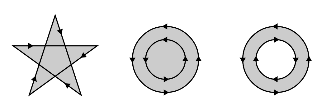
- [
`Aeo,p]ptistrueiff the number of intersections ofpwith a ray cast fromptto infinity in any direction is odd (just make sure the ray doesn't intersectptangently or at a singularity). This is usually refered to as the even-odd rule.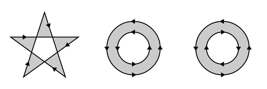
- [
`O o,p]ptistrueiffptis in the outline area ofpas defined by the valueoof typeP.outline. See Outline areas, Segment jointures, Subpath caps, Outline dashes.
Outline areas
The outline area of a path is the union of its subpaths outline areas. A subpath outline area is inside the parallel curves at a distance o.width / 2 of its path segments that are joined accoring to the join style o.join (see below) and closed at the subpath end points with a cap style o.cap (see below). The outline area of a subpath can also be chopped at regular intervals according to the o.dashes parameter (see below).
Segment jointures
The shape of subpath segment jointures is specified in o.join by a value of type P.join. From left to right: 
`Miter, the outer parallel curves are extended until they meet unless the joining angle is smaller thano.miter_anglein which case the join is converted to a bevel.`Round, joins the outer parallel curves by a semicircle centered at the end point with a diameter equal too.width.`Bevel, joins the outer parallel curves by a segment.
Subpath caps
The shape of subpath (or dashes) end points is specified in o.cap by a value of type P.cap. From left to right: 
`Butt, end points are square and extend only to the exact end point of the path.`Round, end points are rounded by a semicircle at the end point with a diameter equal too.width.`Square, end points are square and extend by a distance equal to halfo.width.
Outline dashes
The path outline area can be chopped at regular intervals by spefiying a value (off, pat) of type P.dashes in o.dashes.
The dash pattern pat is a list of lengths that specify the length of alternating dashes and gaps (starting with dashes). The dash offset off is a positive offset that indicates where to start in the dash pattern at the beginning of a subpath.
Examples
Many examples of images and their source can be found in the online version of Vg's test image database. Clicking on the title of an image brings you to its definition.
The following examples show for each renderer the minimal code needed to output an image. This code can also be found in the test directory of the distribution.
Minimal PDF output
The file min_pdf.ml contains the following mostly self-explanatory code. We first define an image and then render it. For the latter step we define some meta-data for the image, a function to print rendering warnings and then render the image on stdout.
open Gg
open Vg

(* 1. Define your image *)

let aspect = 1.618
let size = Size2.v (aspect *. 100.) 100. (* mm *)
let view = Box2.v P2.o (Size2.v aspect 1.)
let image = I.const (Color.v_srgb 0.314 0.784 0.471)

(* 2. Render *)

let () =
  let title = "Vgr_pdf minimal example" in
  let description = "Emerald Color" in
  let xmp = Vgr.xmp ~title ~description () in
  let warn w = Vgr.pp_warning Format.err_formatter w in
  let r = Vgr.create ~warn (Vgr_pdf.target ~xmp ()) (`Channel stdout) in
  ignore (Vgr.render r (`Image (size, view, image)));
  ignore (Vgr.render r `End)
This can be compiled with:
> ocamlfind ocamlopt -package gg,vg,vg.pdf \
                     -linkpkg -o min_pdf.native min_pdf.ml
Minimal SVG output
The file min_svg.ml contains the following mostly self-explanatory code. We first define an image and then render it. For the latter step we define some meta-data for the image, a function to print rendering warnings and then render the image on stdout.
open Gg
open Vg

(* 1. Define your image *)

let aspect = 1.618
let size = Size2.v (aspect *. 100.) 100. (* mm *)
let view = Box2.v P2.o (Size2.v aspect 1.)
let image = I.const (Color.v_srgb 0.314 0.784 0.471)

(* 2. Render *)

let () =
  let title = "Vgr_svg minimal example" in
  let description = "Emerald Color" in
  let xmp = Vgr.xmp ~title ~description () in
  let warn w = Vgr.pp_warning Format.err_formatter w in
  let r = Vgr.create ~warn (Vgr_svg.target ~xmp ()) (`Channel stdout) in
  ignore (Vgr.render r (`Image (size, view, image)));
  ignore (Vgr.render r `End)
This can be compiled with:
> ocamlfind ocamlopt -package gg,vg,vg.svg \
                     -linkpkg -o min_svg.native min_svg.ml
Minimal HTML canvas output
The file min_htmlc.ml contains the following code. Step by step we have:
- Define an image.
- Create and add to the DOM an anchor
athat will parent the canvas. This will allow to download a (usually PNG) file of the image. - Create a canvas element
cand add it as a child ofa. - Create a renderer
rtargeting the canvasc. - Render the image.
- Ask the canvas for an image data URL and set it as the the link of the anchor.
open Gg
open Vg
open Js_of_ocaml

(* 1. Define your image *)

let aspect = 1.618
let size = Size2.v (aspect *. 100.) 100. (* mm *)
let view = Box2.v P2.o (Size2.v aspect 1.)
let image = I.const (Color.v_srgb 0.314 0.784 0.471)

(* Browser bureaucracy. *)

let main _ =
  let d = Dom_html.window ##. document in
  let a = (* 2 *)
    let a = Dom_html.createA d in
    a ##. title := Js.string "Download PNG file";
    a ##. href := Js.string "#";
    a ## (setAttribute (Js.string "download") (Js.string "min_htmlc.png"));
    Dom.appendChild (d ##. body) a; a
  in
  let c = (* 3 *)
    let c = Dom_html.createCanvas d in
    Dom.appendChild a c; c
  in
  let r = Vgr.create (Vgr_htmlc.target c) `Other in   (* 4 *)
  ignore (Vgr.render r (`Image (size, view, image))); (* 5 *)
  ignore (Vgr.render r `End);
  a ##. href := (c ## toDataURL); (* 6 *)
  Js._false

let () = Dom_html.window ##. onload := Dom_html.handler main
This file needs to be compiled to byte code and then js_of_ocaml must be applied. This can be achieved with:
> ocamlfind ocamlc \
-package js_of_ocaml,js_of_ocaml-ppx \
-package gg,vg,vg.htmlc \
-linkpkg -o min_htmlc.byte min_htmlc.ml \
&& js_of_ocaml min_htmlc.byte
Finally we need a minimal HTML file that references our final javascript min_htmlc.js. The following one will do:
<!DOCTYPE html>
<html lang="en">
<head>
  <meta charset="utf-8">
  <meta name="viewport" content="width=device-width,
                                 initial-scale=1.0">
  <script type="text/javascript" defer="defer" src="min_htmlc.js"></script>
  <style type="text/css"> body \{ background-color: black; margin: 3em; \}</style>
  <title>Vgr_htmlc minimal example</title>
</head>
<body>
  <noscript>Sorry, you need to enable JavaScript to see this page.</noscript>
</body>
</html>
Minimal Cairo PNG output
The file min_cairo_png.ml contains the following code. We first define an image and then render it on stdout as a PNG file.
open Gg
open Vg

(* 1. Define your image *)

let aspect = 1.618
let size = Size2.v (aspect *. 100.) 100. (* mm *)
let view = Box2.v P2.o (Size2.v aspect 1.)
let image = I.const (Color.v_srgb 0.314 0.784 0.471)

(* 2. Render *)

let () =
  let res = 300. /. 0.0254 (* 300dpi in dots per meters *) in
  let fmt = `Png (Size2.v res res) in
  let warn w = Vgr.pp_warning Format.err_formatter w in
  let r = Vgr.create ~warn (Vgr_cairo.stored_target fmt) (`Channel stdout) in
  ignore (Vgr.render r (`Image (size, view, image)));
  ignore (Vgr.render r `End)
This can be compiled with:
>  ocamlfind ocamlopt -package gg,vg,vg.cairo \
                      -linkpkg -o min_cairo_png.native min_cairo_png.ml
Minimal Cairo memory buffer rendering
The file min_cairo_mem.ml contains the following code. We first define an image and then render to a bigarray buffer.
open Gg
open Vg

(* 1. Define your image *)

let aspect = 1.618
let size = Size2.v (aspect *. 100.) 100. (* mm *)
let view = Box2.v P2.o (Size2.v aspect 1.)
let image = I.const (Color.v_srgb 0.314 0.784 0.471)

(* 2. Render *)

let raster, stride =
  let res = 300. /. 25.4 (* 300dpi in dots per mm *) in
  let w = int_of_float (res *. Size2.w size) in
  let h = int_of_float (res *. Size2.h size) in
  let stride = Cairo.Image.(stride_for_width ARGB32 w) in
  let data = Bigarray.(Array1.create int8_unsigned c_layout (stride * h)) in
  let surface = Cairo.Image.(create_for_data8 data ARGB32 ~stride w h) in
  let ctx = Cairo.create surface in
  Cairo.scale ctx ~x:res ~y:res;
  let target = Vgr_cairo.target ctx in
  let warn w = Vgr.pp_warning Format.err_formatter w in
  let r = Vgr.create ~warn target `Other in
  ignore (Vgr.render r (`Image (size, view, image)));
  ignore (Vgr.render r `End);
  Cairo.Surface.flush surface;
  Cairo.Surface.finish surface;
  data, stride
> ocamlfind ocamlopt -package cairo2,gg,vg,vg.cairo \
-linkpkg -o min_cairo_mem.native min_cairo_mem.ml